Removing the chinese wifi from Midea/Mr Cool minisplit with ESPHome.
Why do this?
We have multiple AC units on my property and 3 of those are from MRCool, this also worked on our Midea UShaped unit as well. We are all about NOT having devices with unknown code on our network, especially ones from china. Using a few parts and the Midea Integration from ESPHome we were able to strip out their module and have direct, local control over my split units.
DIY NOTICE: ALL INFORMATION PROVIDED HERE IS PROVIDED AS-IS. WE ARE NOT TO BE HELD LIABLE IF YOU BREAK SOMETHING, CATCH SOMETHING ON FIRE, OR WHATEVER IF YOU DECIDE TO DO SOMETHING IN THIS GUIDE.
Need Help?
We have extensive IT and Home Automation knowledge. If you are wanting a custom IoT/Home Automation solution or just need help with your project Contact Us to get a quote. Our hourly labor charge is $50/hr for technical services like this.
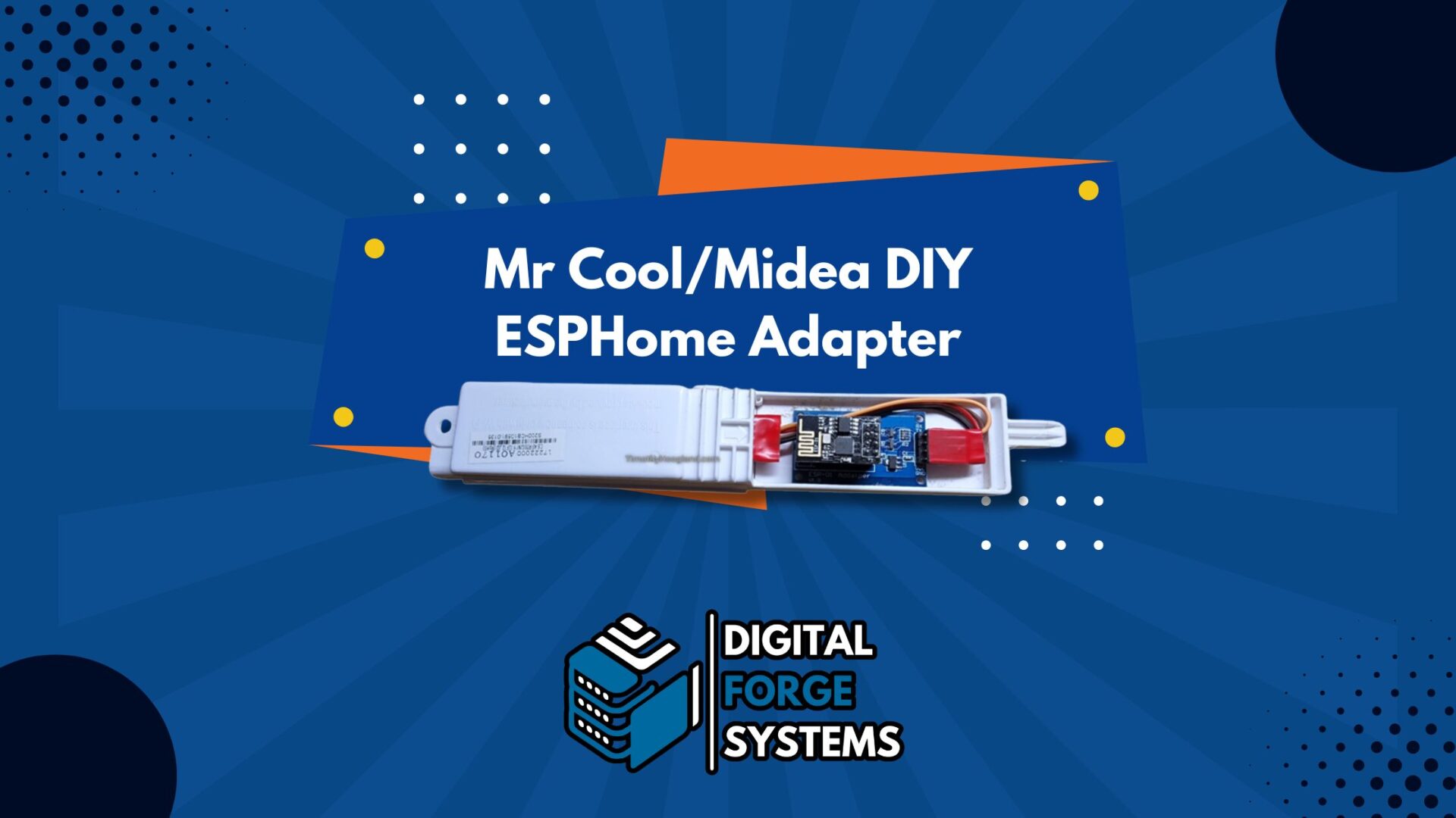
Making the Adapter
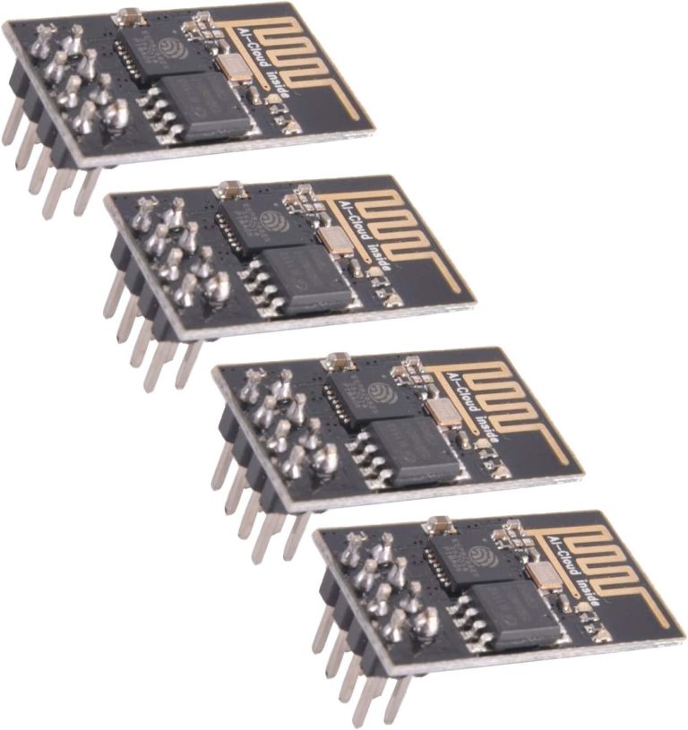
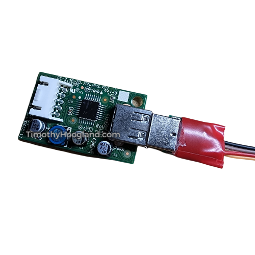
Instead of bodging up some PCB we used off the shelf parts and the ONLY soldering involved is the 4 wires to the USB breakout board to the ESP-01 adapter board. That adapter board has a built in 5V to 3.3V step down and the proper pullups to use the cheap ESP-01 modules with it. Click on the pictures to go to amazon to get the parts (these are affiliate links) that we used for this build.
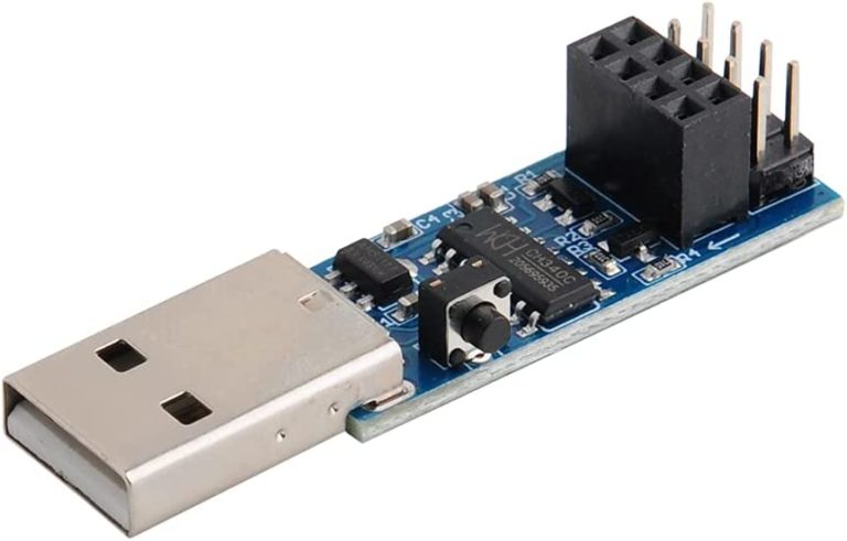
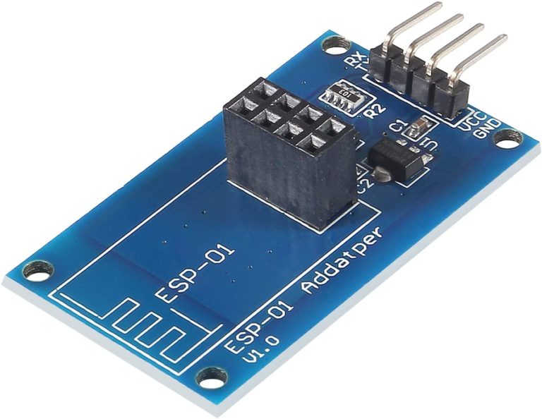
If you look on the ESP-01 Adapter board you will see it has TX RX, VCC, and GND labeled.
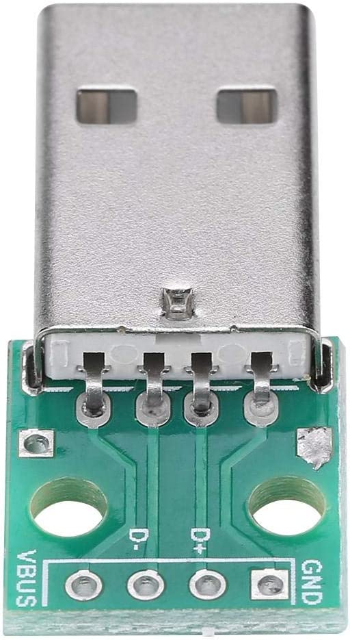
Connecting the ESP-01 Adapter board to the USB Breakout Adapter Board
- Connect the GND to GND solder pad on the USB breakout adapter
- Connect VCC to the VBUS solder pad on the USB breakout adapter
- Connect TX to the D+ solder pad on the USB breakout adapter
- Connect RX to the D- solder pad on the USB breakout adapter
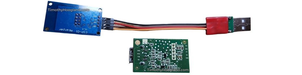
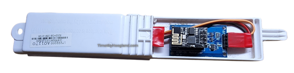
Now this wiring listed works for my MRCool branded units and they are kind enough to label them on the PCB that accepts their wifi dongle. We removed and disconnected the whole wifi dongle “box” from the unit and disconnected it to work on it on my bench. Now if you don’t get communication between the split unit later on in the guide when we setup ESPHome then you will want to swap the TX and RX pins.
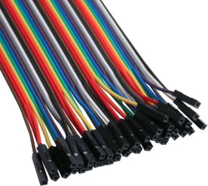
If your split unit PCB is not labeled like ours was then you’ll have a 50/50 shot of getting the TX RX correct. It won’t hurt anything to get it swapped, it just won’t work. We used Dupont jumper wires with one end cut off and stripped to make the connection between the two. Once we had the USB breakout end soldered up we put some hot glue on there and then wrapped it in electrical tape while it was still hot to make our own strain relief for the wires.
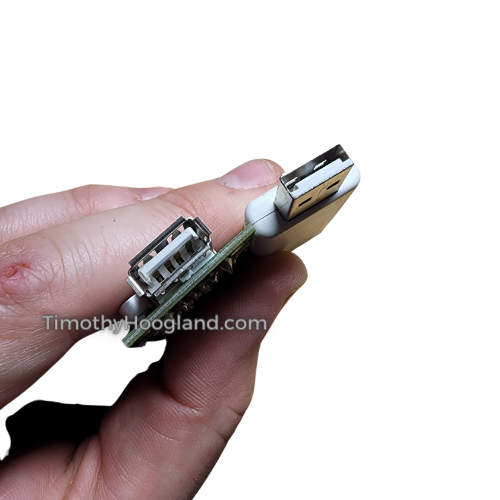
“USB” Connector – Force it in
If you notice the USB connector on mine is not really USB. It has extra edges on it to prevent insertion of a normal USB device in. Luckily you can just force it in and it works.
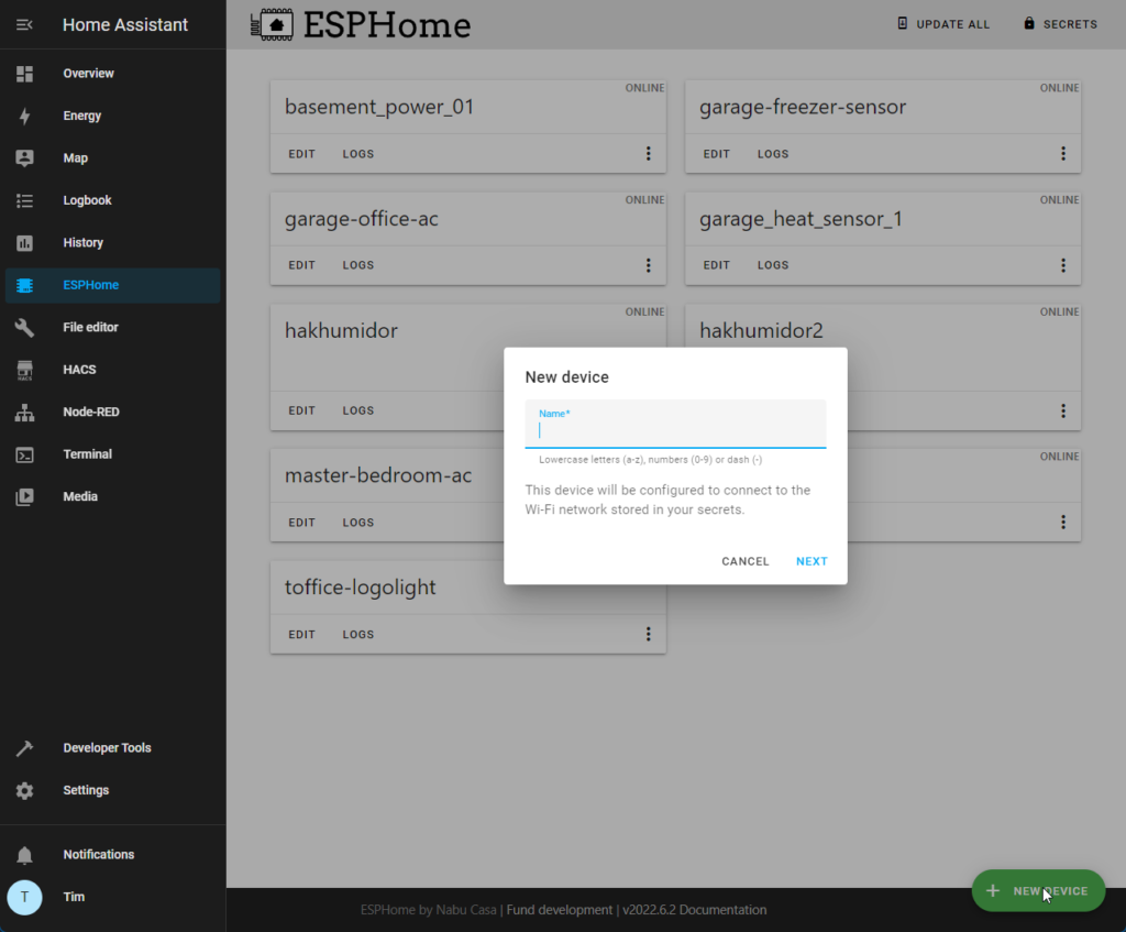
ESPHome Setup
Now we are going to assume you know how to use ESPHome. If you don’t then read their documentation. At this point put the ESP-01 into the programmer and plug it into your PC. Then use the ESPHome Wizard to do the initial flashing.
Below is the YAML code we used for the setup and we did have to manually add certain modes for my unit. It does have auto-detect but on my MRCool units it didn’t work 100%. There is also code added to allow you to disable and enable the annoying beep they make when you change a setting.
Basically your mileage may vary and read the ESPHome docs on the Midea Air integration to learn how to fine tune it for your particular unit if our example doesn’t work. We also intentionally omitted the HEAT mode since we don’t use it here. Once you have the device flashed you can install it on the ESP-01 adapter board that we wired up earlier and put it in the unit. We did ours with the power on but if you are paranoid you can cut power to the minisplit before you plug in the new adapter. Its all 5V DC so its not going to hurt you.
Once its all installed and you check the ESP logs to see if its communicating with your split unit then go ahead and add it to Home Assistant as you would any other ESPHome device using the Home Assistant integrations feature.
esphome:
  name: garage-office-ac

esp8266:
  board: esp01_1m

# Disable logging over UART (required)
logger:
  baud_rate: 0

# Enable Home Assistant API
api:
  encryption:
    key: "REDACTED"

ota:
  password: "REDACTED"

wifi:
  ssid: !secret wifi_ssid
  password: !secret wifi_password

  # Enable fallback hotspot (captive portal) in case wifi connection fails
  ap:
    ssid: "Garage-Office-Ac"
    password: "REDACTED"

captive_portal:

# UART settings for Midea dongle (required)
uart:
  tx_pin: GPIO1         # hardware dependant
  rx_pin: GPIO3         # hardware dependant
  baud_rate: 9600

# Main settings
climate:
  - platform: midea
    name: Garage Office AC     # Use a unique name.
    autoconf: false
    beeper: false
    visual:
      min_temperature: 16 °C
      max_temperature: 30 °C
      temperature_step: 1 °C
    supported_modes:            # All capabilities in this section detected by autoconf.
      - FAN_ONLY                # This capability is always used.
      - COOL
      - DRY
    supported_presets:          # All capabilities in this section detected by autoconf.
      - BOOST
    supported_swing_modes:
      - VERTICAL                # This capability is always used.

switch:
  - platform: template
    name: Garage Office AC Beeper
    icon: mdi:volume-source
    optimistic: true
    turn_on_action:
      midea_ac.beeper_on:
    turn_off_action:
      midea_ac.beeper_off: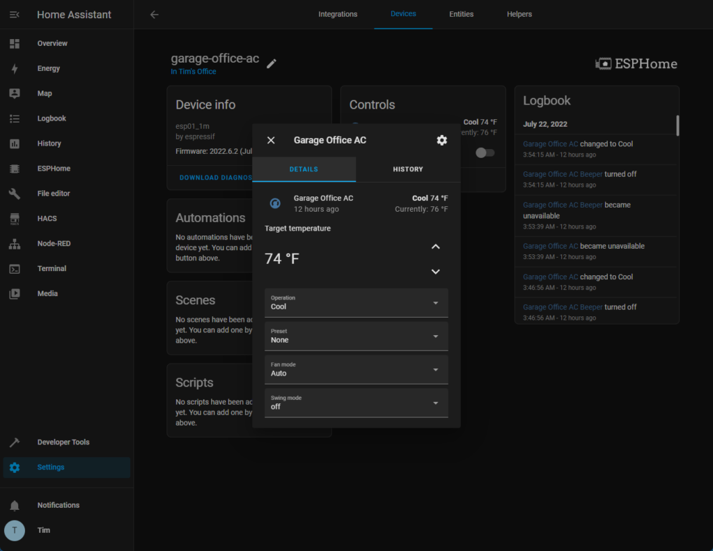
This isn’t a SUPER detailed guide but this should be more than enough to get you going if you know what you are doing 🙂 Now go enjoy one less chinese code run wifi device on your network!
~Tim Hoogland